Target detection algorithm for basketball robot based on IBN-YOLOv5s algorithm – Scientific Reports

YOLOv5 algorithm is a kind of deep learning algorithm, which is more widely used in the field of TD. The study is in Chap. 3, firstly, the TD method of basketball robot is analyzed, and secondly, the TD algorithm of basketball robot is optimized. Chapter 3 is broken into two parts, the first part is to analyze the robot TD based on laser detection, and the second part is to study the robot TD algorithm that combines laser detection with YOLOv5s algorithm.
Robotic target detection analysis combining laser detection with YOLOV5
The routine activities of robots need to be performed by sensing equipment, and object detection is a common means for robots to perceive the surrounding environment. The laser detection method is one of the precise methods for object detection, which is realized by relying on a laser transmitter for detection. The laser transmitter emits light pulses during ranging, and the distance between the target and the robot can be calculated through Eq. (1).
In Eq. (1), d denotes the distance between the robot and the target, c denotes the speed of light, and t denotes the round-trip time of the laser. The UST-20LX is a small laser range sensor commonly used for robot navigation and obstacle avoidance, which calculates the distance between an object and the sensor by emitting laser pulses and measuring the time difference of the light that is reflected back to the sensor18,19. The detection angle of the UST-20LX is very wide, covering a field of view of more than half a circle of the field of view. Within this range, it emits a total of 1081 laser pulses, each of which is capable of measuring distance information over a very small angular interval with an angular resolution of 0.25 degrees between these pulses. In practice, the data should be processed with a focus on the front of the robot. The 240th to 840th light pulses, corresponding to the field of view in front of the robot from 15 degrees to 165 degrees, can cover most of the obstacles and objects that may be encountered on the robot’s path of travel, and only these light pulses need to be paid attention to when processing the data, as shown in Fig. 120,21.
TD using the laser detection algorithm requires traversing the ranging information of each light wave, but considering the actual size of the competition field and the robot’s localization strategy, the laser detection algorithm treats all distances exceeding 4 m as 4 m to reduce external noise. The algorithm recognizes the target by checking the change in the distance value of the light wave, and once the mutation value is found to be greater than a specified threshold, the variables start and end are set to mark the possible target. If both start and end are non-zero, the target is likely to be detected, but it needs to be further examined by the angular difference between start and end, and only the angular difference within the preset threshold is recognized as the target. Finally, the position of the target is calculated from the ranging value and angle of the intermediate light wave in the range of start and end. If the target is not detected, the above steps are repeated until the TD is completed. The laser detection algorithm can calculate the distance and angle between the target and the robot in the TD, where the distance calculation is shown in Eq. (2).
$$object\_dis=data\left\lfloor {\frac{{start+end}}{2}} \right\rfloor$$
(2)
In Eq. (2), object_dis denotes the target object distance. The angle calculation is shown in Eq. (3).
$$object\_angle=data\left( {\frac{{start+end}}{2}} \right) \times {0.25^ \circ } – {0.45^ \circ }$$
(3)
In Eq. (3), object_angle denotes the angle of the target object. The laser detection algorithm can only detect the presence of an object in practical applications, and cannot judge whether the object is the target of the robot. The YOLOv5 algorithm carries out real-time TD through the camera video stream, identifying various types of objects in the image and their position information. The combination of the laser detection algorithm and YOLOv5 enables TD with both high-precision localization and judgment of object categories. However, the detection targets of the two detection methods may not be the same, for this problem, the angle of the target object detected by the YOLOv5 algorithm can be compared and analyzed with the angle detected by the laser. When the difference between the two angles is within the acceptable error range, it can be recognized that this target is the designated target that the robot needs to detect. The fusion of the laser detection algorithm and the YOLOv5s algorithm is divided into three parts, the first is the calculation of the angle of the target. The second is the fusion of the laser detection information and the detection information of the YOLOv5s algorithm. The last is the realization of the TD system. The calculation of the angle of the target needs to be calculated by the camera field of view angle, the information included in YOLOv5s includes the type of the target and the coordinates of the target, after the system receives this information, it needs to determine whether there is a target that needs to be monitored in the information, and if it exists, the area of the nearest target is calculated according to the Eq. (4), so as to facilitate the subsequent detection.
$$object\_area=\left( {{x_{\hbox{max} }} – {x_{\hbox{min} }}} \right) \times \left( {{y_{\hbox{max} }} – {y_{\hbox{min} }}} \right)$$
(4)
In Eq. (4), object_area indicates the area of the target, x indicates the maximum and minimum coordinates of the target in the direction of x; y indicates the maximum and minimum coordinates of the target in the direction of y. In addition to the area of the target, the coordinates of the center point of the target also need to be calculated, and the calculation of the horizontal coordinates of the center point is shown in Eq. (5).
$$t\arg et\_bbox\_centerX=0.5 \times \left( {t\arg et\_bbox.{x_{\hbox{max} }}+t\arg et\_bbox.{x_{\hbox{min} }}} \right)$$
(5)
The calculation of the vertical coordinates of the center point is shown in Eq. (6).
$$t\arg et\_bbox\_centerX=0.5 \times \left( {t\arg et\_bbox.{y_{\hbox{max} }}+t\arg et\_bbox.{y_{\hbox{min} }}} \right)$$
(6)
Since the information included in YOLOv5s is located in the upper left corner of the image as a whole, the computed center point of the target is also biased towards the upper left corner, as shown in Fig. 2.
When the center point of the target is located to the left of the center point of the image, the angle of the target is shown in Eq. (7).
$$\begin{gathered} t\arg et\_angle={90^ \circ }+\left( {{u_0} – t\arg et\_bbox\_centerX} \right)*{d_u} \hfill \\ ={90^ \circ }+\left( {320 – t\arg et\_bbox\_centerX} \right)*\left( {{{45}^ \circ }/640} \right) \hfill \\ \end{gathered}$$
(7)
In Eq. (7), (u0, v0) means the coordinates of the image center point. When the calibration column is located to the right of the image center point, the angle of the calibration column is shown in Eq. (8).
$$\begin{gathered} t\arg et\_angle={90^ \circ } – \left( {t\arg et\_bbox\_centerX – {u_0}} \right)*{d_u} \hfill \\ ={90^ \circ } – \left( {t\arg et\_bbox\_centerX – 320} \right)*\left( {{{45}^ \circ }/640} \right) \hfill \\ \end{gathered}$$
(8)
After calculating the angle between the target and the calibration column by YOLOv5s, the angle calculated by the algorithm is compared with the angle calculated by the laser detection, and if the error between the two is less than the pre-set threshold, it can indicate that the same target is detected by the two detection methods. If the YOLOv5s algorithm determines that the target object is a ball, the robot continues to advance until it picks up the ball and completes the throwing action. The study achieved high-precision object detection of basketball robots by integrating laser detection algorithms and improved YOLOv5s algorithms. The laser detection algorithm calculates the target distance based on the time difference between laser emission and reception, while the YOLOv5s algorithm identifies the target and its position by processing the camera video stream. During the fusion process, the target angles detected by the two methods are compared. When the difference is within the preset error range, it is confirmed to be the same target. To address the differences and potential conflicting results of different detection methods, a confidence based weighting mechanism was introduced, and the algorithm flow was optimized to reduce computational resource consumption. In addition, robustness under extreme lighting conditions was also considered, and the overall performance of the system was improved by combining multiple sensor data. This fusion method not only improves the accuracy of object detection, but also enhances the robustness of the system in dynamic and complex environments.
Research on improved YOLOv5s algorithm based on IBN
YOLOv5s is a version of the YOLO series of TD algorithms, developed and maintained by the open source community, and optimized mainly for speed and accuracy. YOLOv5 in the YOLO series, the performance and speed balance is suitable for application scenarios that require fast reasoning and have model size limitations, such as mobile devices or embedded systems22. The core strength of the YOLO series of algorithms lies in its single-inference TD capability, i.e., it can detect all targets in the image and their category and location information after a single global inference to the image.YOLOv5 is the first iteration of the series in this YOLOv5 is an iteration in this series, which goes a step further to gain improvements in architecture and efficiency.YOLOv5 first matches the labeled target frames with 9 anchors, ignoring the frames with low matching thresholds, which are considered as background. Then, the grid containing its center and the two closest grids are found for the remaining target boxes. Using the anchor points of these three grids that match the size of the target box, TD is performed, as denoted in Fig. 3(a). For TD, target box prediction needs to be performed by the target box grid, with its matching anchors, and this prediction process is a regression process, as shown in Fig. 3(b), and the whole regression process is a fine-tuning process.
In YOLOv5s algorithm, when predicting the target frame, it is necessary to judge the effect of the prediction frame and take the best prediction frame as the final result. The study uses Non-Maximum Suppression (NMS) algorithm as a method to judge the effect of prediction frames. The algorithm judges the prediction frames by the intersection ratio of the target frames and the confidence level. The intersection ratio is the ratio of the intersection of two frames to the concatenation, as shown in Eq. (9).
$$IOU=\frac{{A \cap B}}{{A \cup B}}$$
(9)
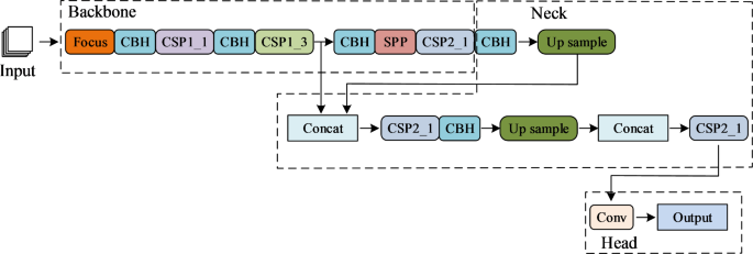
The overall YOLOv5s model is divided into four parts, which are Input, Backbone, Neck, and Head. Where Neck is located in the middle of the model, which can fuse the features extracted in each stage of Backbone to raise the performance of the network, and the overall structure is shown in Fig. 4.
The main structure of Backbone consists of four basic modules, including convolutional layer, batch normalization layer, and HardSwish activation function (Conv, Batch Normalization, HardSwish, CBH) module. Second is the Focus module, which is responsible for slicing the input image and rearranging the spatial blocks of the graph. The third is the CSP module, which realizes the reorganization of the features by modifying the traditional residual block structure, by splitting the feature graph, partially crossing it, and later merging it, the structure of this module is denoted in Fig. 5.
Finally, there is the Spatial Pyramid Pooling Network (SPP) module, which reduces the algorithm’s image size requirements when processing images, allowing the network to process input images of any size, reducing distortion problems caused by cropping or scaling of the image. SPP can capture multi-scale features from different levels, which helps detect targets of different sizes and enhances the algorithm’s recognition ability for targets of various sizes. The SPP structure is integrated into the backend of the network as part of feature extraction, enabling YOLOv5 to leverage the advantages of the SPP structure and improve the performance of object detection. The Head section of YOLOv5s, which is the result of the algorithm’s Output section. Robot in TD, depending on the distance, the size of the object size changes in the image. Head part divides the target object stage features into three scales, large, medium and small, by introducing multi-scale prediction, and the feature maps of each stage have the same size.BN is a technique commonly used in deep learning to speed up the training process of neural networks and improve their performance. Batch normalization mitigates the internal covariate bias by normalizing the inputs of each layer in the network, the normalization expression of BN is shown in Eq. (10)23,24.
$$BN\left( x \right)=\gamma \left( {\frac{{x – {\mu _C}\left( x \right)}}{{{\sigma _C}\left( x \right)}}} \right)+\beta$$
(10)
In Eq. (10), γ and β denote the affine parameters for training and learning; μc (x) denotes the mean value of all image feature channels; σc (x) denotes the standard deviation of all image feature channels. The computation of μc (x) is shown in Eq. (11).
$${\mu _C}\left( x \right)=\frac{1}{{NHW}}\sum\limits_{{n=1}}^{N} {\sum\limits_{{h=1}}^{H} {\sum\limits_{{w=1}}^{W} {{x_{nchw}}} } }$$
(11)
In Eq. (11), N denotes the image width; H denotes the image height; W denotes the amount of samples in the training batch; C denotes the color channel. The calculation of the color channel σc (x) is shown in Eq. (12).
$${\sigma _C}\left( x \right)=\sqrt {\frac{1}{{NHW}}\sum\limits_{{n=1}}^{N} {\sum\limits_{{h=1}}^{H} {\sum\limits_{{w=1}}^{W} {{{\left( {{x_{nchw}} – {\mu _C}\left( x \right)} \right)}^2}} +\varepsilon } } }$$
(12)
In Eq. (12), ε denotes a constant. Instance normalization (IN) is a normalization technique in deep learning, which was initially proposed for the style migration task and has gradually been applied in other computer vision tasks. The main idea of instance normalization is to normalize each feature map individually, and IN ignores the statistical information of inter-batch samples, and normalizes the computation based only on the statistical information of individual samples themselves. The IN representation is shown in Eq. (13).
$$IN\left( x \right)=\gamma \left( {\frac{{x – {\mu _{nC}}\left( x \right)}}{{{\sigma _{nC}}\left( x \right)}}} \right)+\beta$$
(13)
In Eq. (13), μnc (x) represents the mean value of the feature channel of a single image; σnc (x) denotes the standard deviation of the feature channel of a single image. The calculation of μnc (x)is shown in Eq. (14).
$${\mu _{nC}}\left( x \right)=\frac{1}{{HW}}\sum\limits_{{n=1}}^{N} {\sum\limits_{{h=1}}^{H} {\sum\limits_{{w=1}}^{W} {{x_{nchw}}} } }$$
(14)
The calculation of σnc (x) is shown in Eq. (15).
$${\sigma _{nC}}\left( x \right)=\sqrt {\frac{1}{{HW}}\sum\limits_{{n=1}}^{N} {\sum\limits_{{h=1}}^{H} {\sum\limits_{{w=1}}^{W} {{{\left( {{x_{nchw}} – {\mu _C}\left( x \right)} \right)}^2}} +\varepsilon } } }$$
(15)
In response to the challenge of target detection for basketball robots in diverse game environments, the YOLOv5s model is improved by introducing the IBN-Net module to enhance its generalization ability. The IBN-Net module consists of two structures: IBN-Net-a introduces IN and replaces some BN in the residual module, maintaining the diversity of feature maps while ensuring the non-interference of identity mapping paths; IBN-Net-b further optimizes residual learning, both aimed at improving the accuracy of the model in detecting target objects under different lighting and environmental conditions. There are three ways of adding the IBN-Net module to the YOLOv5s model as shown in Fig. 6.
Figure 6(a) shows the improved scheme of introducing the IBN-Net module in the CBH module, and Fig. 6(b) and (c) both show the improved scheme of introducing the IBN-Net module in the residual module. The YOLOv5s network structure designed for research is shown in Fig. 7.
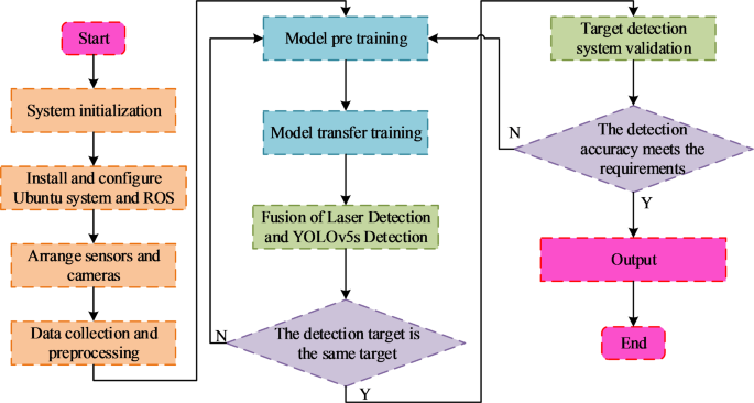
The improvement of YOLOv5s network structure in research and design is divided into three parts as a whole. The first part is data sampling and data planning, the second part is image features output during the data sampling stage, and the third part is the head part of YOLOv5s network structure. The implementation process of the algorithm based on improved YOLOv5s network and laser detection fusion designed for research is shown in Fig. 8.
When implementing this algorithm, it is necessary to first initialize the basketball robot, install the Ubuntu system and Robot Operating System (ROS), and arrange sensors and cameras. After completing the robot debugging, you can start collecting data and preparing for algorithm training. The collected raw data still needs to be preprocessed before it can be used for algorithm training. The training of the algorithm is divided into two parts. The first part is the pre training of the model, and the second part is the transfer training of the model. After the training is completed, the laser detection results are fused with the detection results of the YOLOv5s network, and the detection targets of the two are judged to be the same. After determining whether they are the same target, the target detection effect is judged. If they meet the requirements, the results are output. If they do not meet the requirements, the algorithm model is retrained.
Related
Arizona State fires women’s basketball coach after another losing season
Two days after being bounced from the Big 12 women's basketball tournament in the second round, Arizona State has fired women's basketball coach Natasha Adair.
Where to watch Auburn vs Alabama men’s basketball streaming free;…
The SEC men’s basketball regular season draws to a close as the No. 1 ranked Auburn Tigers battle the No. 7 ranked Alabama Crimson Tide in this fierce in-stat
Auburn vs. Alabama prediction, odds, time: 2025 college basketball picks,…
The top-ranked Auburn Tigers will look to get back into the win column when they battle
Preview: UConn men’s basketball vs. Seton Hall | 2:30 p.m.,…
It’s the last day of the regular season in the Big East, with five games on Saturday that will shape Big East Tournament seeding and in UConn’s case, cou


